Solutions
Products
-
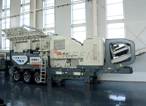
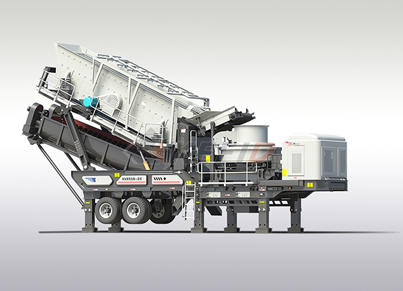
Primary mobile crushing plant
-
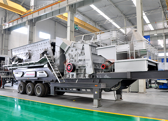
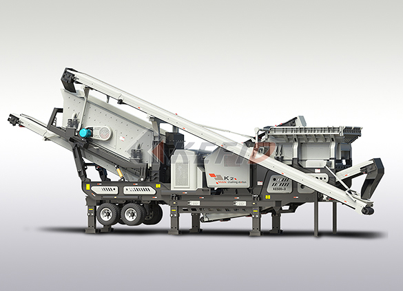
Independent operating combined mobile crushing station
-
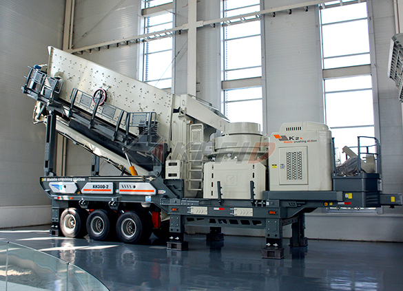
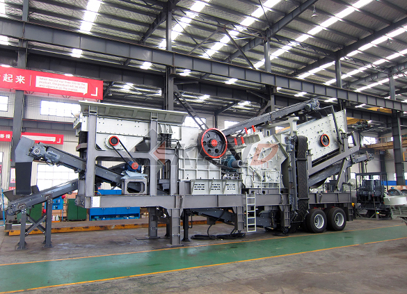
Mobile secondary crushing plant
-
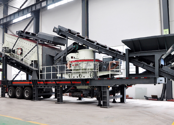
Fine crushing and screening mobile station
-
Fine crushing & washing mobile station
-
Three combinations mobile crushing plant
-
Four combinations mobile crushing plant
-
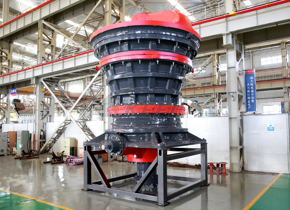
HGT gyratory crusher
-
C6X series jaw crusher
-
JC series jaw crusher
-
Jaw crusher
-
HJ series jaw crusher
-
CI5X series impact crusher
-
Primary impact crusher
-
Secondary impact crusher
-
Impact crusher
-
HPT series hydraulic cone crusher
-
HST hydraulic cone crusher
-
CS cone crusher
-
VSI6S vertical shaft impact crusher
-
Deep rotor vsi crusher
-
B series vsi crusher
-
Vertical grinding mill
-
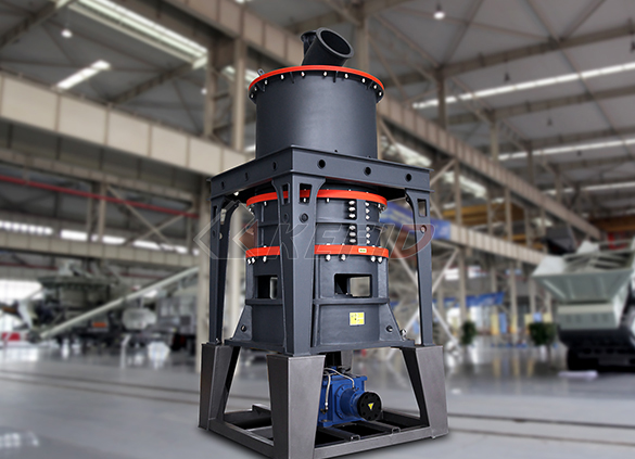
Ultra fine vertical grinding mill
-
MTW european grinding mill
-
MB5X158 pendulum suspension grinding mill
-
Trapezium mill
-
T130X super-fine grinding mill
-
Micro powder mill
-
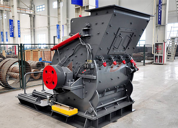
European hammer mill
-
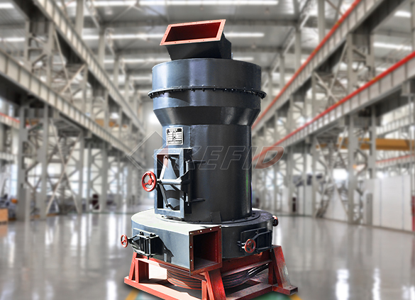
Raymond mill
-
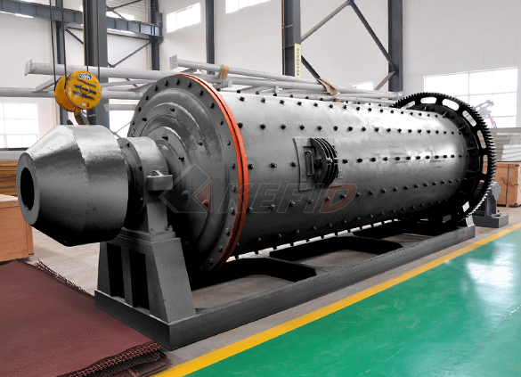
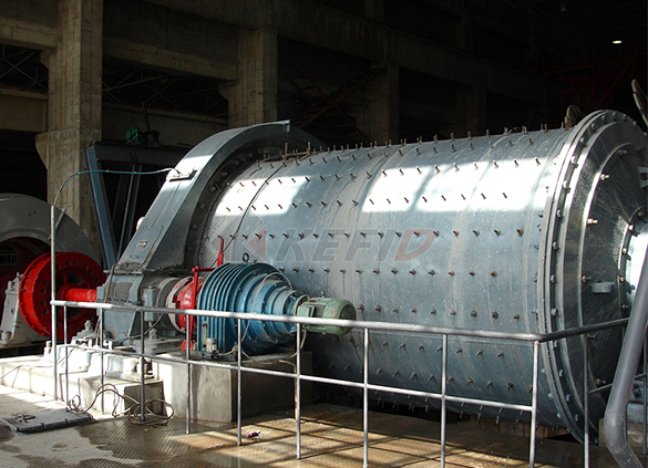
Ball mill
-
GF series feeder
-
FH heavy vibrating feeder
-
TSW series vibrating feeder
-
Vibrating feeder
-
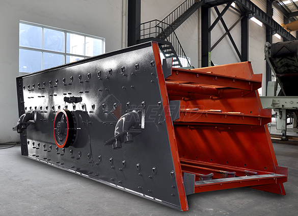
Vibrating screen
-
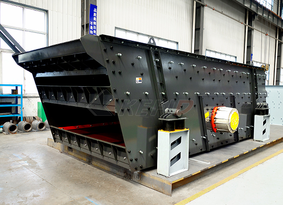
S5X vibrating screen
-
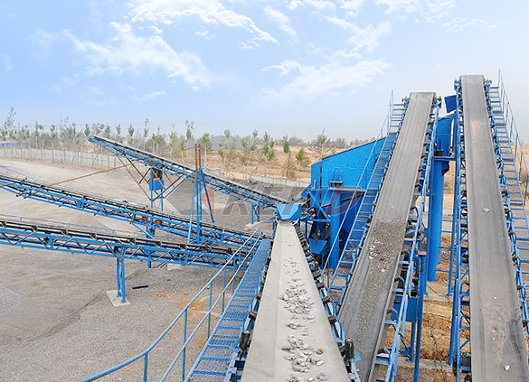
Belt conveyor
-
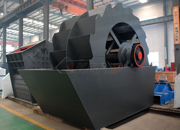
Wheel sand washing machine
-
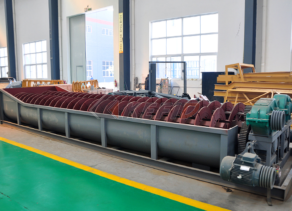
Screw sand washing machine
-
Rod mill
-
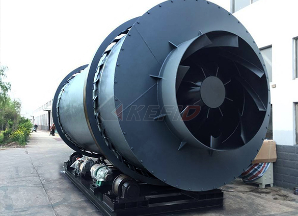
Dryer
-
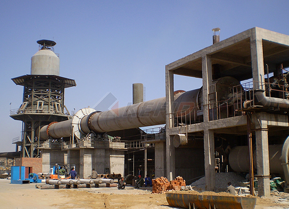
Rotary kiln
-
Wet magnetic separator
-
High gradient magnetic separator
-
Dry magnetic separator
-
Flotation machine
-
Electromagnetic vibrating feeder
-
High frequency screen
Industrial sector Reliable and efficient cement production
of the cement industry that show their strengths particularly in critical applications We support you in selecting the right lubricant and are with you as partner from changeover to routine checks, from the lubricant sampling and the setup of lubrication systems to the optimisation of lubricant quantities30032018 Lubrication in the cement industry offers some unique challenges It’s not so much the type of equipment that is the issue but the environment in which the machinery is operating, which can vary from season to season depending on the plant’s locationLubrication Strategies for the Cement IndustryCement Plant LubricationA brief on typical equipment and lubricantsCement is manufactured by either a Wet process or Dry process In the wet process, water is addedand resultant slurry is transported through “closed conveyers” to the KilnPrior to a Lubrication survey, we can breakdown the lubrication at Cement Plants into 5 segments i Cement plant lubrication SlideShareflow diagram of typical lubrication arrangement for a cement mill flow diagram of typical lubrication arrangement for a cement mill FL ball mill for cement grinding Lubrication of dry barrel hydrants 7Lubrication Chart Of Dry Grinding Ball MillEvery Cement Plant operates differently and will have its own existing lubrication strategies, preferences (maybe based on historical issues), historical problems which are not insurmountable, Planned Maintenance requirements, management structure and type of workforce available, but there will be an optimum solution in respect of the lubricants selected, the equipment utilized to apply those Cement Industry Lubrication Machinery

Cement Manufacturing Process Simplified Flow
15032017 Cement manufacturing process components of a cement plant from quarry to kiln to cement mill Skip to content Menu Home; Resources Civil PowerPoint Presentations Civil ppts; Cement Manufacturing Process Simplified Flow Chart March 15, 2017 May 11, 2013 by Johnny13012014 Mill Lubrication System 1 OBJECTIVES: To identify the definition and importance of a hydraulic lubrication system To be familiarized with the lubricant and equipment used in the system To understand the process and various design of Mill lubrication system To identify some problems encountered by the system, and formulate some recommendation to help fix the problemsMill Lubrication System SlideShareCEMENT MILL OPTIMISATION CASE STUDY VK Batra*, the optimisation of a ball mill circuit and is supported with typical case study done by HOLTEC in a 15 mio t/a cement plant Mill vent flow : 972 m 3/min Separation air at separator outlet : 5599 m 3/minPROCESS DIAGNOSTIC STUDIES FOR CEMENT MILL 04062012 The lubrication and hydraulic systems continuously provide clean, cool lubrication and hydraulic fluid to the components at the proper pressure, temperature and flow The lubrication system used for aeroderivative type gas turbines is different from that in an industrial gas turbine, in that a scavenge (vacuum) system is added in the latter, to return lube oil to the sump under flight conditionsLubrication Systems an overview ScienceDirect Material flow during processing includes: (a) particle size reduction, (b) premixing, (c) mixing, (d) pelleting, and (e) sacking Coarse ingredients pass over a permanent magnet which removes tramp metal and then through a hammer mill which reduces particle size to the desired screen analysisChapter 17 Material Flow in Feed Manufacturing 1
Lubrication Systems an overview ScienceDirect
04062012 The lubrication and hydraulic systems continuously provide clean, cool lubrication and hydraulic fluid to the components at the proper pressure, temperature and flow The lubrication system used for aeroderivative type gas turbines is different from that in an industrial gas turbine, in that a scavenge (vacuum) system is added in the latter, to return lube oil to the sump under flight conditionsTypical applications include heavy industry, metal working plants, pulp and paper, mining, mineral processing and cement factories, deck cranes, power plants, sugar mills and more These systems utilize two main lines that are supplied alternately with lubricant Advantages Ideal for many lubrication points over long distancesLubrication Amet Industries1 Straight line flow 2 U shaped flow 3 In a building designed for distribution, to adapt to another use 4 To place permanent equipment and avoid later interference 5 Distribution center 6 Cellular flow 7 Modular work flow 8 Clean room for sterile or aseptic liquids Examples of plant layout and design Jackson Productivitydiagram of a typical seal is provided as Figure 2 212 Freshwater Lubrication On very rare occasions in port, freshwater may be used for lubricating the shaft seal on submarines This occurs on approximately four submarines per year, for one week each 4Phase I Final Rule and Technical Development Document of Flow control systems (Fig 6) control the supply of seal gas to the seal by regulating the seal gas flow through an orifice upstream of the seal This can be accomplished with a simple needle valve, or through the use of a differential pressure control valve monitoring pressures on either side of the orificeDESIGN, OPERATION, AND MAINTENANCE CONSIDERATIONS FOR

Handbook for chain engineering Design and construction
Tel: +49 89 769091500 Fax: +49 89 769091198 sales@iwis iwis 3 Joh Winklhofer Beteiligungs GmbH Co KG Company Headquarters, Parent of the independent subsidiary companies,pillowblock bearings A typical sideentering mixer is shown in Figure 215 Both belt drives and bearing types are discussed later in this chapter 21215 BottomEntering Mixers Bottomentering mixers are usually the same basic drive arrangement as a turbine mixer, but mounted on the bottom of the tankCHAPTER 21 Mechanical Design of Mixing Equipmentexamples of product layout, Paper mills, dairies, cement factories, and automotive assembly plants , Auto manufacturing product layout use specialized machines that are set up once to perform a specific operation for a long period of time on one product, this machines requires great expense and long down times To change over to a new product designLayout for manufacturing facilitiesDiagram of typical fuel, cooling, lubrication, and starting systems Typical arrangement of metal enclosed switchgear Current flow in instrument transformers OPERATION, MAINTENANCE AND REPAIR OF AUXILIARY GENERATORSSuggested wiring arrangement SELECTOR SWITCH HI SPEED CONTACTOR OVERLOAD OVERLOAD LO SPEED CONTACTOR These diagrams are current at the time of publication, check the wiring diagram supplied with the motor *NOTE: Refer to the motor manufacturer’s data on the motor for wiring diagrams on standard frame Ex e, Ex d etc motorsWIRING DIAGRAMS STANDARD MOTORS
Lubrication Systems an overview
04062012 The lubrication and hydraulic systems continuously provide clean, cool lubrication and hydraulic fluid to the components at the proper pressure, temperature and flow The lubrication system used for aeroderivative type gas turbines is different from that in an industrial gas turbine, in that a scavenge (vacuum) system is added in the latter, to return lube oil to the Typical applications include heavy industry, metal working plants, pulp and paper, mining, mineral processing and cement factories, deck cranes, power plants, sugar mills and more These systems utilize two main lines that are supplied alternately with lubricant Advantages Ideal for many lubrication points over long distancesLubrication Amet Industries17082020 Lubrication supply arrangements can generally be grouped into three categories: 1) selfcontained units for supplying lubrication to individual bearings; 2) circulating systems dedicated to a single piece of equipment such as a motor, a turbine or a compressor; and 3) centralized systems in manufacturing plants, paper mills and metal working 1 Following is a Matching Lube Oil Systems to Machinery what typical facilities or equipment look like NonABB photo source given below picture other pictures and illustrations are ABB Edition 13 Oslo, June 2006 Håvard Devold ©2006 ABB ATPA Oil and Gas Except as otherwise indicated, all materials, Oil and gas production handbook ed1x3a5 compexamples of product layout, Paper mills, dairies, cement factories, and automotive assembly plants , Auto manufacturing product layout use specialized machines that are set up once to perform a specific operation for a long period of time on one product, this machines requires great expense and long down times To change over to a new product designLayout for manufacturing facilities
Cement manufacturing process SlideShare
10062014 Cement manufacturing process 1 1What is cement ? 2History 3Overveiw of Cement Manufacturing process 4Overveiw of Kiln process 5Why burn wastes ? 2 Portland Cement A hydraulic cement made by finely powderising the clinker produced by calcining to incipient fusion a mixture of argillaceous and calcareous materials pillowblock bearings A typical sideentering mixer is shown in Figure 215 Both belt drives and bearing types are discussed later in this chapter 21215 BottomEntering Mixers Bottomentering mixers are usually the same basic drive arrangement as a turbine mixer, but mounted on the bottom of the tankCHAPTER 21 Mechanical Design of Mixing EquipmentDiagram of typical fuel, cooling, lubrication, and starting systems Typical arrangement of metal enclosed switchgear Current flow in instrument transformers “Polarity” marks show instantaneous flows OPERATION, MAINTENANCE AND REPAIR OF AUXILIARY GENERATORSA free customizable manufacturing org chart template is provided to download and print Quickly get a headstart when creating your own manufacturing org chartIt is designed on the basis of manufacturing enterprise's specific structureManufacturing Org Chart Free Manufacturing pellet mill A pellet mill is not designed to pellet these materials, let alone the animal stomach to digest them The pelleting process starts with a bin (Figure 1, Item 1) in which the mixture of mash is stored From there, the mash will flow by gravity into the pellet mill The Pelleting Process CPM